COMPUTER SCIENCE CAFÉ
  • WORKBOOKS
  • BLOCKY GAMES
  • GCSE
    • CAMBRIDGE GCSE
  • IB
  • A LEVEL
  • LEARN TO CODE
  • ROBOTICS ENGINEERING
  • MORE
    • CLASS PROJECTS
    • Classroom Discussions
    • Useful Links
    • SUBSCRIBE
    • ABOUT US
    • CONTACT US
    • PRIVACY POLICY
  • WORKBOOKS
  • BLOCKY GAMES
  • GCSE
    • CAMBRIDGE GCSE
  • IB
  • A LEVEL
  • LEARN TO CODE
  • ROBOTICS ENGINEERING
  • MORE
    • CLASS PROJECTS
    • Classroom Discussions
    • Useful Links
    • SUBSCRIBE
    • ABOUT US
    • CONTACT US
    • PRIVACY POLICY
TOPIC 10 | LOGIC SYMBOLS AND FUNCTIONS
ON THIS PAGE
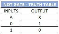
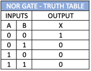
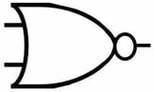
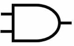
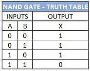
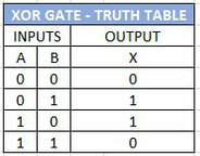
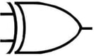
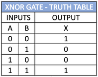
10.1 Identify and use the standard symbols for logic gates
10.2  Define and understand the functions of the logic gates: Including:
– NOT
– AND
– OR
– NAND
– NOR
– XOR (EOR)
– the binary output produced from all the possible binary inputs
• NOT is a single input gate
• All other gates are limited to two inputs
ALSO IN THIS SECTION
LOGIC SYMBOLS AND FUNCTIONS
USING LOGIC GATES
Picture
WHAT ARE LOGIC GATES
Logic gates are a major component of a computers hardware, there are usually thousands of logic gates in the circuits of computers. Logic gates act as a switch and control the flow of electricity through them depending on the combination of input they receive.

The types of logic gates discussed in this section are:
  • NOT Gate ( represented with Ā)
  • OR Gate  (represented with  A + B)
  • NOR Gate
  • AND Gate (represented with A x B or A · B )
  • NAND Gate
  • XOR Gate ( Represented with ⊕ )

Each of the various working of the logic gates can be illustrated in Truth Tables. As circuits get big and multiple logic gates or used together it is good practice to use truth tables to trace the outcomes. Most truth tables will replace the text ON and OFF with 1 and 0.
THE NOT GATE
The NOT gate is the only gate with just one input. The NOT gate simply reverses the input, if the input is ON then the OUTPUT is OFF, if the input is OFF then the output is on.
Picture
NOT GATE
The image above illustrates a NOT gate, it is the circle that symbolises the NOT and this circle is also used on other gates discussed later. Below is the truth table for the NOT gate.
Picture
NOT GATE TRUTH TABLE
The NOT gate can be represented in Boolean Algebra by placing a combining overbar over the values to pass through a NOT gate, so NOT A can be represented as Ā
THE OR GATE
The OR gate will give an output value of ON if any of the inputs are ON.
Picture
OR GATE
The OR gate can be viewed as the mathematical equivalent of addition. 
A + 0 = A
A + A = A
0 + 0 = 0
A + Ā = 1
Notably different from normal mathematics as in boolean logic the above shows the the sum of a variable will equal the variable, for example 1 + 1 = 1
Picture
OR GATE TRUTH TABLE
THE NOR GATE
The NOR Gate or NOT OR Gate will have an output if none of the inputs are 1. The NOR gate has a circle on the output to define the NOT part of the gate. You can see this as the opposite of an OR gate.
Picture
NOR GATE TRUTH TABLE
Picture
NOR GATE
THE AND GATE
The AND gate will only give an output when both inputs are ON, in other works input one AND input two need to be ON to make the output ON.
Picture
AND GATE
Picture
AND GATE TRUTH TABLE
The AND gate can be viewed are the mathematical equivalent to multiplication.
A x 0 =  0
A x 1 = A
​A x A = A
A x Ā = 0
THE NAND GATE
The NAND Gate or NOT AND Gate will have an output when the two inputs are not ON. Or with a three input NAND gate when all 3 inputs are not ON.
Picture
NAND GATE TRUTH TABLE
Picture
THE NAND GATE
THE XOR GATE
The XOR gate or eXclusive OR will only produce an output it the two inputs are different values.
Picture
XOR TRUTH TABLE
Picture
THE XOR GATE
THE XNOR GATE
Picture
The exclusive not or will be 1 if both input values are the same. 
LOGIC GATE QUESTIONS
1: What does the NOT gate do?
A. Outputs true if both inputs are true
B. Inverts the input signal
C. Outputs true if either input is true
D. Outputs true if both inputs are false

2: In an AND gate, the output is true when:
A. Any one of the inputs is true
B. None of the inputs are true
C. Both inputs are true
D. Both inputs are false

3: Which gate will have a true output when either of its inputs is true?
A. NOT
B. AND
C. OR
D. NAND

4: What is the output of a NAND gate when both inputs are true?
A. True
B. False
C. The same as the input
D. Can't be determined

5: The NOR gate outputs true when:
A. Both inputs are true
B. Either input is true
C. Neither input is true
D. Inputs are different

6: An XOR (Exclusive OR) gate outputs true if:
A. Both inputs are true
B. Both inputs are false
C. The inputs are different
D. The inputs are the same

7: Which statement is true about the OR gate?
A. It outputs false only when both inputs are false
B. It always outputs true
C. It outputs true only when both inputs are true
D. It inverts the input signal

8: If an AND gate has an input of 1 and 0, the output will be:
A. 1
B. 0
C. The same as the input
D. Can't be determined

9: In a NAND gate, if one input is 0 and the other is 1, the output will be:
A. 1
B. 0
C. The same as the input
D. Inverted

10: Which gate behaves like an OR gate followed by a NOT gate?
A. AND
B. XOR
C. NOR
D. NAND
Picture
SUGGESTIONS
We would love to hear from you
SUBSCRIBE 
To enjoy more benefits
We hope you find this site useful. If you notice any errors or would like to contribute material then please contact us.