COMPUTER SCIENCE CAFÉ
  • WORKBOOKS
  • BLOCKY GAMES
  • GCSE
    • CAMBRIDGE GCSE
  • IB
  • A LEVEL
  • LEARN TO CODE
  • ROBOTICS ENGINEERING
  • MORE
    • CLASS PROJECTS
    • Classroom Discussions
    • Useful Links
    • SUBSCRIBE
    • ABOUT US
    • CONTACT US
    • PRIVACY POLICY
  • WORKBOOKS
  • BLOCKY GAMES
  • GCSE
    • CAMBRIDGE GCSE
  • IB
  • A LEVEL
  • LEARN TO CODE
  • ROBOTICS ENGINEERING
  • MORE
    • CLASS PROJECTS
    • Classroom Discussions
    • Useful Links
    • SUBSCRIBE
    • ABOUT US
    • CONTACT US
    • PRIVACY POLICY
TOPIC 10 | USING LOGIC GATES
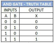
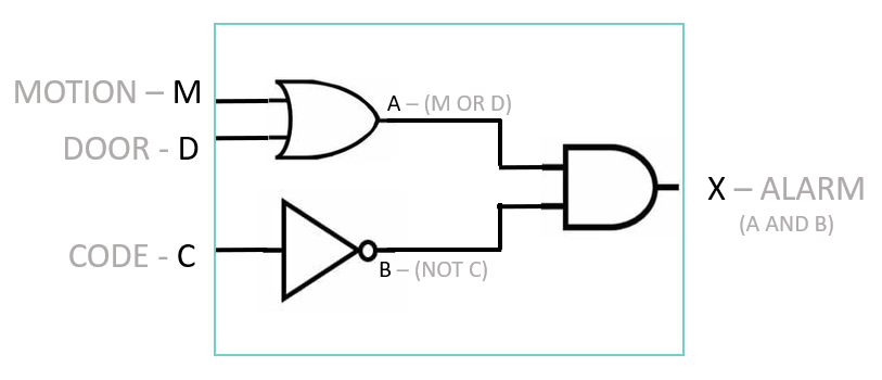
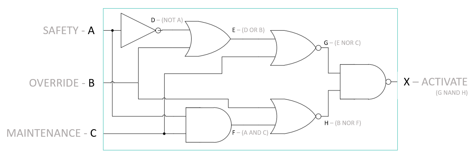
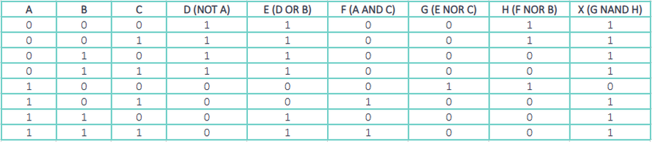
3 (a) Use logic gates to create given logic circuits from a:
 (i) problem statement
 (ii) logic expression
 (iii) truth table
3(b) Complete a truth table from a:
 (i) problem statement
 (ii) logic expression
 (iii) logic circuit

3(c) Write a logic expression from a:
 (i) problem statement
 (ii) logic circuit
 (iii) truth table
ALSO IN THIS SECTION
LOGIC SYMBOLS AND FUNCTIONS
USING LOGIC GATES

Picture
WHAT IS A PROBLEM STATEMENT
A problem statement typically defines a specific scenario or requirement that needs to be addressed or solved using a combination of logic gates. It outlines the conditions and desired outcomes, which can be translated into a logical circuit using appropriate gates. The problem statement serves as the basis for designing a digital circuit that meets the specified criteria.

Example of a Problem Statement
Design a security system logic circuit for a storage room that triggers an alarm under two conditions: either when motion is detected inside the room, or when the door is opened without a security code being entered. However, the alarm should not sound if the correct security code is entered, regardless of motion detection or door status.
WHAT IS A LOGIC EXPRESSION
A logic expression, also known as a Boolean expression, is a mathematical notation that specifies a combination of logic operations performed on logical variables. In the realm of computer science and digital electronics, these expressions are used to represent the function of logic gates and circuits. Here are some characteristics of Logic Expressions.
  • Based on Boolean Algebra | Logic expressions are rooted in Boolean algebra, a branch of algebra that deals with true and false values, typically represented as 1 and 0, respectively.
  • Use of Logical Operators | These expressions employ operators such as AND (⋅), OR (+), NOT (¬), NAND, NOR, XOR, and XNOR to combine one or more logic variables.
  • Variables and Constants | The expressions consist of variables (like A, B, C) that represent inputs and outputs of logic gates, and constants (0 for false, 1 for true).
  • Represent Logic Circuits | Every logic circuit can be described by a logic expression, and conversely, every logic expression can be implemented as a logic circuit.

Example
For a simple AND gate with two inputs A and B, the logic expression is:

Expression: Y = A AND B
In Boolean Notation: Y = A ⋅ B
WHAT IS A LOGIC CIRCUIT
A logic circuit is a physical arrangement of logic gates designed to perform a specific logical operation. It's the cornerstone of digital electronics, found in computers, calculators, and many other electronic devices.
  • Based on Binary System | Logic circuits operate using binary numbers (0s and 1s), representing two states: ON (1) and OFF (0).
  • Composed of Logic Gates | These are the basic building blocks of logic circuits. Gates like AND, OR, NOT, NAND, NOR, XOR, and XNOR process binary inputs to produce a binary output.
  • Perform Logical Operations | Each circuit performs a specific function, determined by the arrangement and type of gates used.
  • Can Be Simple or Complex | They range from basic circuits with a single gate to complex integrated circuits with millions of gates.
  • Used in Computing and Digital Electronics | Logic circuits form the basis of the central processing unit (CPU), memory, and other components in computers.
WHAT IS A TRUTH TABLE
​A truth table is a mathematical table used to determine whether a logic statement is true or false. In the context of digital electronics and computer science, it is primarily used to represent the output of a logic circuit for every possible combination of inputs.

​As can be seen on the previous page each logic can be represented with their own truth table. The first thing you should notice is that the input values are listed in a logical binary order, this ensures that you do not make any mistakes when creating the input values and helps maintain consistency so all truth tables are easy to read. For n inputs, there will be 2^n combinations.​
Picture
Notice the pattern when listing binary, the left hand column will always read down 1 zero then 1 one, the next column will be 2 zero's then 2 one's the third column 4 zero's then 4 ones, this pattern continues as you add column. The other reason to list the binary this way is if you convert the binary value to normal numbers then you are simply counting from Zero upwards. You can also work out the total possible input combinations by doing 'Number of inputs ^2'. For example the logic gate in the diagram above has 2 inputs so 2^2=4, there is a total of 4 possible combinations to the input values.

NOTE: MANY STUDENTS LOSE MARKS OR GET THE ANSWER WRONG BECAUSE THEY DO NOT LIST THE INPUTS USING THIS METHOD.
CREATING A LOGIC CIRCUIT AND TRUTH TABLE
Creating a logic circuit involves several steps, from understanding the problem to designing and testing the circuit.
  1. Understand the Scenario | Carefully read the problem statement to understand what the circuit is supposed to achieve. Identify the inputs and the desired output.
  2. Determine the Required Logic | Based on the scenario, decide which logical operations (AND, OR, NOT, etc.) are needed to achieve the desired output.
  3. Select the Appropriate Gates | Choose the logic gates that will fulfil the required logical operations.
  4. Draw the Circuit Diagram | Sketch a diagram of the circuit. Place the gates in the correct arrangement and connect them with lines representing the flow of inputs and outputs.
  5. Label Inputs and Outputs | Clearly label all inputs and the output in the diagram.
  6. Create a Truth Table | This is a table showing all possible combinations of inputs and their corresponding outputs. It helps in verifying the functionality of your circuit.
  7. Test and Validate | Check if the circuit works as intended for all input combinations. You can use simulation software for complex circuits.​
CREATE A LOGIC CIRCUIT FROM A TRUTH TABLE
​
EXAMPLE PROBLEM STATEMENT 1
Create a circuit that turns on a light (output) when it is either night-time (input A) or the room is occupied (input B), but not both.
  1. Understand the Scenario | You need a circuit with two inputs (night-time and room occupancy) and one output (light).
  2. Determine the Required Logic | The light should be on if either one condition is true, but not both. This is an exclusive OR operation.
  3. Select the Appropriate Gates | Choose an XOR gate.
  4. Draw the Circuit Diagram | Draw a diagram with two inputs leading to an XOR gate, and the output from this gate is the light.
  5. Label Inputs and Outputs | Label the inputs as A (night-time) and B (room occupancy) and the output as the light.
Picture
   6: Create a Truth Table | The truth table below is a method of visually displaying the outcomes of a logic gate or all of the           possible outcomes of a logic circuit.   ​
A (NIGHT TIME)
B (OCCUPIED)
X = LIGHT (A XOR B)
O
O
O
O
1
1
1
O
1
1
1
O

​   7. Test and Validate | Check the circuit against all possible input combinations to ensure it works correctly.
The above example is a simple solution to a simple problem statement that only requires the use of one logic gate. In the next example we look at a slightly more complex problem statement and provide tips on how to break down the problem to create a logic circuit and truth table.
EXAMPLE PROBLEM STATEMENT 2
Design a security system for a storage room that triggers an alarm under two conditions: either when motion is detected inside the room, or when the door is opened without a security code being entered. However, the alarm should not sound if the correct security code is entered, regardless of motion detection or door status.
Breaking Down the Problem Statement
  • Motion Detection | If motion is detected, the alarm should be triggered.
  • Door Status and Security Code | If the door is opened without entering the correct security code, the alarm should be triggered.
  • Override Condition | If the correct security code is entered, the alarm should not be triggered, irrespective of motion or door status.

INPUTS
M (Motion Detected): 1 if motion is detected, 0 otherwise.
D (Door Opened): 1 if the door is opened, 0 otherwise.
C (Correct Code Entered): 1 if the correct code is entered, 0 otherwise.

OUTPUT
Alarm (A): The alarm system. (1 if the alarm should be triggered, 0 if it should not)
Logic Circuit Design:

WORKING OUT WHAT GATES ARE NEEDED
Step 1 | Combine Motion and Door Status
  • Logic Needed | The alarm should trigger if either motion is detected or the door is opened.
  • Gate Used | OR gate.
  • Reasoning | An OR gate outputs 1 (true) if either of its inputs is 1. This matches our need to trigger the alarm if either motion is detected (M = 1) or the door is opened (D = 1).
  • Logic Expression | M OR D

Step 2 | Consider the Security Code
  • Logic Needed | The alarm should not trigger if the correct security code is entered.
  • Gate Used | NOT gate.
  • Reasoning | A NOT gate inverts its input. If the correct code is entered (C = 1), the NOT gate will output 0, indicating that the alarm should not trigger.
  • Logic Expression | NOT C

Step 3 | Combine the Conditions
  • Logic Needed | The alarm should trigger based on motion or door status, but this should be overridden if the correct code is entered.
  • Gate Used | AND gate.
  • Reasoning | An AND gate outputs 1 only if both its inputs are 1. By connecting the output of the OR gate (M OR D) and the output of the NOT gate (NOT C) to an AND gate, the alarm will trigger only if there is motion or the door is opened and the correct code is not entered.
  • Final Logic Expression | (M OR D) AND (NOT C)
Picture
Notice in the logic diagram above A and B have been added as intermediate values, doing this is good practice as it allows you to methodically label and trace the circuit in a truth table.
​ 
Create a Truth Table | The truth table below is a method of visually displaying the outcomes of a logic gate or all of the           possible outcomes of a logic circuit.  
​
M
D
C
A (M OR D)
B (NOT C)
X - ALARM
(A AND B)
O
O
O
O
1
O
O
O
1
O
O
O
O
1
O
1
1
1
O
1
1
1
O
O
1
O
O
1
1
1
1
O
1
1
O
O
1
1
O
1
1
1
1
1
1
1
O
O
When listing binary values for the inputs in a truth table, it's important to follow a logical and systematic order. For a scenario with three inputs, you should list the binary values starting from 000 and incrementing up to 111. This sequence follows the standard binary counting method, ensuring that all possible combinations of inputs are covered systematically. Be aware that failing to list the binary values in this correct order could result in your answer being marked incorrect. This methodical approach is essential for accuracy and completeness in your work with logic circuits.
EXAMPLE PROBLEM STATEMENT 3
Design a control system for a specialized manufacturing robot. The robot should activate a specific function (X) based on the following conditions: The function should be active if either the safety sensor (A) is not triggered or the manual override (B) is engaged, but not if the system is in maintenance mode (C). Additionally, this function should also be active if both the safety sensor is triggered and the system is not in maintenance mode, but not if the manual override is disengaged.

​Breaking Down the Problem Statement
INPUTS
  • A (Safety Sensor) | A represents the safety sensor (1 if triggered, 0 if not).
  • B (Manual Override) | B represents the manual override (1 if engaged, 0 if not).
  • C (Maintenance Mode) | C represents the maintenance mode (1 if in maintenance, 0 if not).

OUTPUT
  • Activate robot (X) | 1 if the system should activate, 0 if not.

WORKING OUT WHAT GATES ARE NEEDED
Step 1 | Safety sensor or override
  • Logic Needed | Check if the safety sensor is not triggered or the manual override is engaged. Ensure the system is not in maintenance mode
  • Gate Used | NOT gate for A / OR gate for NOT A and B / NOR gate combining the output of the OR gate with C.
  • Logic Expression | ((NOT A OR B) NOR C)

Step 2 | Safety sensor and not in maintenance mode
  • Logic Needed | Check if both the safety sensor is triggered and the system is not in maintenance mode. Ensure the manual override is not disengaged.
  • Gate Used | AND gate for A and C / NOR gate combining the output of the AND gate with B.
  • Logic Expression | ((A AND C) NOR B)

Step 3 | Combining both parts
  • Logic Needed | First Part NAND Second Part. Combine the two conditions: (1) safety sensor not triggered/manual override engaged, not in maintenance, and (2) safety sensor triggered, not in maintenance, manual override not disengaged.
  • Gate Used | NAND gate combining the outputs of the two NOR gates.
  • Final Logic Expression | X=((NOT A OR B) NOR C) NAND ((A AND C) NOR B)​
Picture
The truth table below represents the circuit - remember to list the intermediate values (D, E, F, G, H) in your truth tables to avoid simple mistakes being made.
Picture
CREATING A LOGIC DIAGRAM FROM A LOGIC TABLE
To create a logic circuit from a given truth table you first need to create a boolean expression. To create a boolean expression you only need to look at the values from the truth table that have an output of 1. 
A
B
C
X
1
1
1
1
1
1
1
1
1
1
1
1
1
1
Step 1: Identify the Rows with Output '1'
Look at the rows in the truth table where the output (Y) is 1. These rows will help us determine the logic needed for the circuit.

From the table above, the rows where X is '1' are:
  • A = 1, B = 0, C = 0
  • A = 1, B = 1, C = 1

​Step 2: Write the Boolean Expression
Writing the boolean expression for each of the scenarios where X = 1. There are three rules to follow.
  • If the Value of the input is 0 then use a NOT gate
  • AND the values of each line together
  • OR each or the lines together

So for the first line A = 1, B = 0, C = 0 we can create the boolean expression of:
((A AND NOT B) AND NOT C))

For the second line A = 1, B = 1, C = 1 we can create the boolean expression of:
((A AND B) AND C)

Next - combine the two statements together with an OR gate

((A AND NOT B) AND NOT C)) OR ((A AND B) AND C)

​Now you are ready to create the Logic circuit
Picture
Question from CIE Specimen P2
Picture
SCENARIO
Design a digital system for a library's automated lighting and security system. The lights should turn on if either it is dark outside (D) or if there are people in the library (P). The security alarm should be activated if it is dark and the library is supposed to be closed (C), but there are still people inside (P).

INPUTS
  • Dark Outside (D): 1 if it's dark outside, 0 otherwise.
  • People in Library (P): 1 if people are present, 0 if the library is empty.
  • Library Closed (C): 1 if the library is supposed to be closed, 0 otherwise.

OUTPUTS
  • Lights (L): 1 if lights should be on, 0 if off.
  • Security Alarm (S): 1 if the alarm should be activated, 0 if not.

TASKS
  1. Create the 2 Logic Expressions for this scenario
  2. Create a truth table for this scenario
  3. Create the logic circuit for this scenario
Picture
SUGGESTIONS
We would love to hear from you
SUBSCRIBE 
To enjoy more benefits
We hope you find this site useful. If you notice any errors or would like to contribute material then please contact us.